“I’m not going there to die. I’m going to find out if I’m really alive.”
Man, what a journey this summer has been. I’ve learned so much this summer about all sorts of amazing technologies, and you guys have been there to see me through it all, so thank you to anyone who may have stumbled across this wacky blog on the internet, and to my professor, Lucas von Hollen, who inspired me to try out all sorts of different disciplines that I would never have touched before starting this journey. But nothing lasts forever, and time stands still for no man, so let’s get right into it.
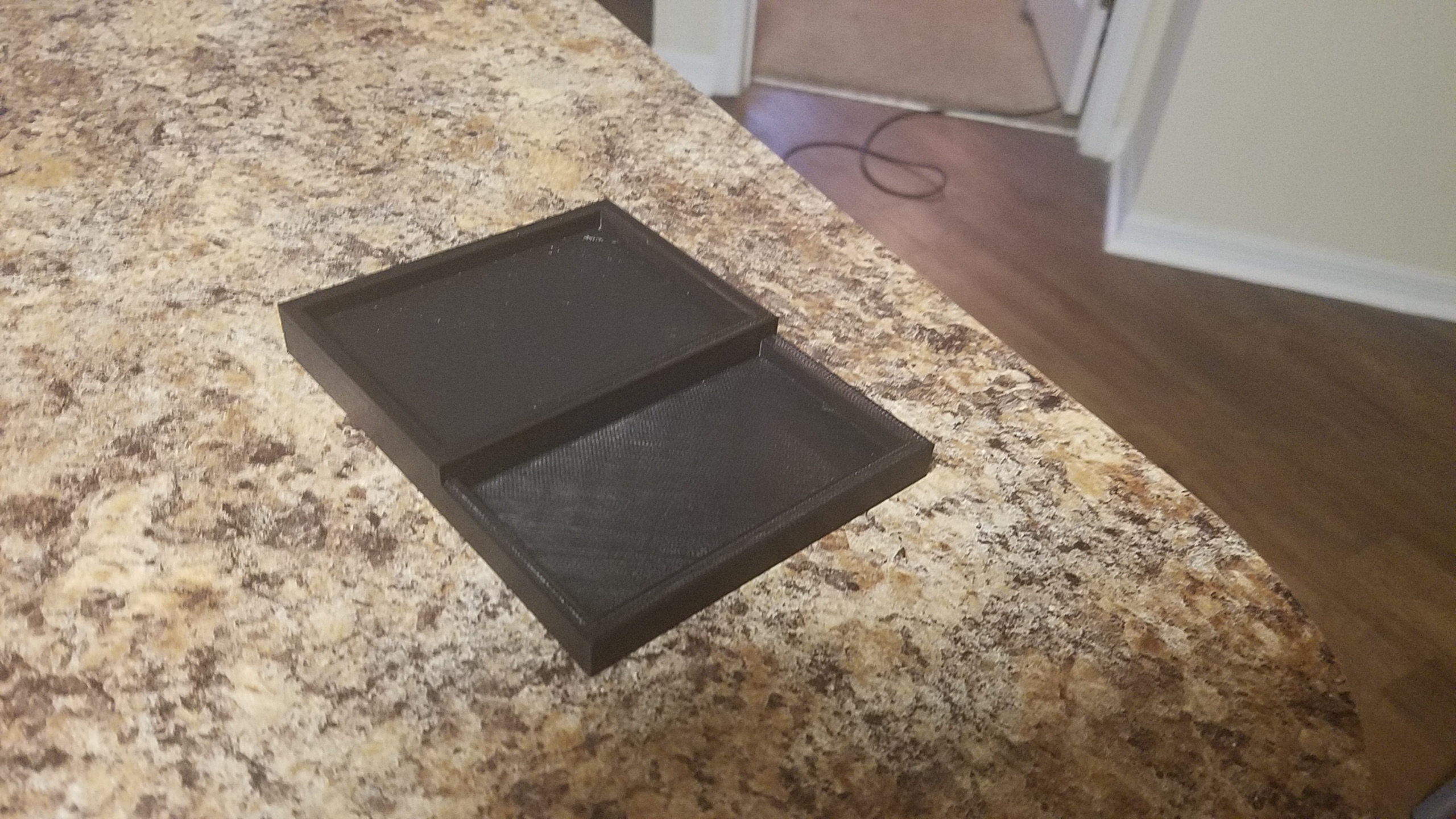
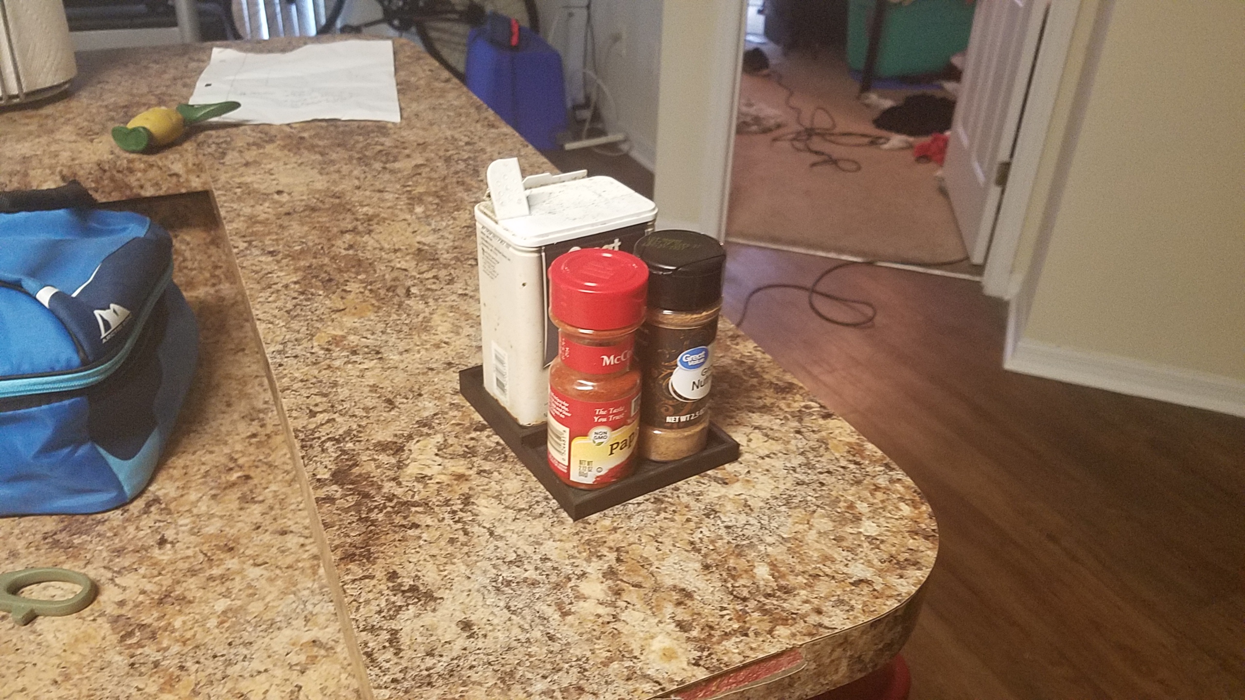
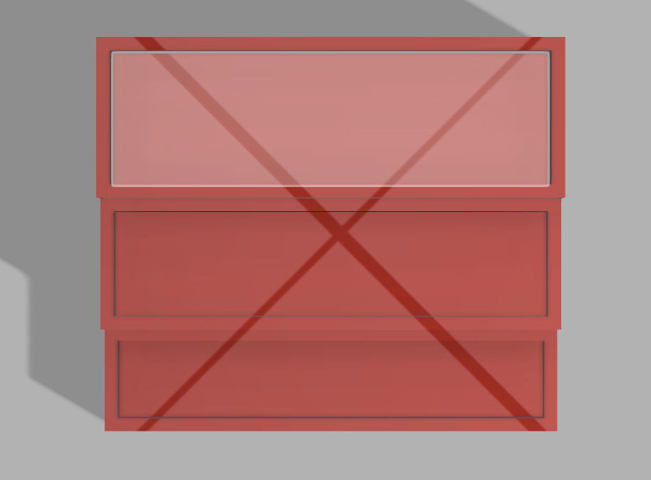
Last time I had touched upon my 3D model for the spice rack was a little over three weeks ago. There I had shown a model in the shape of an ascending stair case with three steps. I had measured it to perfectly fit at least five spices on each row, but I would soon find out that this model was waaaayyyy to large for a 3D printer. So I went to the drawing board and developed, instead, a compromise, which consisted of a two step system which would better fit a 3D printer. However, this too was much to large. I ended up going through about 6 different iterations until I finally found a size that would fit the 3D printer, but at this point, my creation was severely handicapped. But, I suppose it is best to show rather than tell, so here is my finished product:
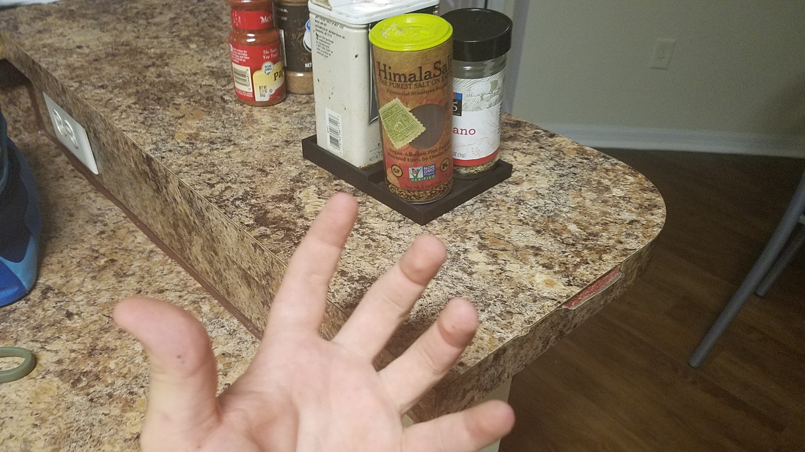
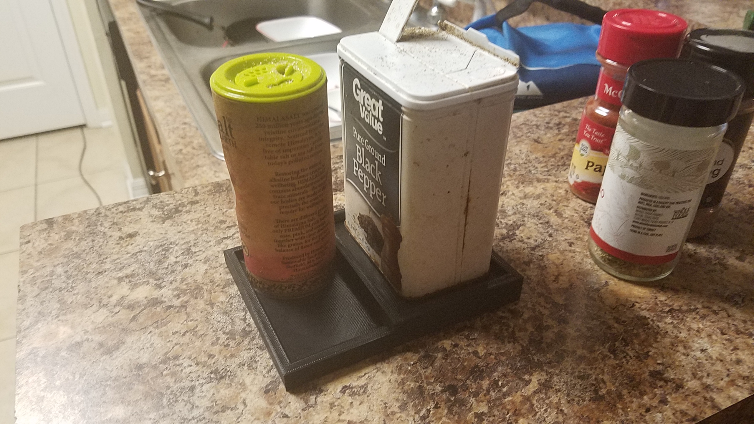
Yea, it’s pretty small. The top row could only hold one large spice and the bottom one could only hold, at max, two spices.
And even then, two is kinda pushing it.
Yea, this project was a pain in the ass. First off, yes, I had to go through six different iterations for designs, each one increasingly smaller than the last. Now, it might of benefited me to print the spice rack in parts, but I am a stubborn jackass and wanted this to print as one design without the need for super gluing and the such. Not only that, but I had to attempt to print this three different times! Now, I never screwed up a print, it would just not even start printing. Now before you ask, no, I did not attempt to print a .STL file, all files sent to the printers were .gcodes. The problem I had was with the software I was using to splice the .STL, which was Dremel. Apparently, Dremel sucks really bad, and the cure for such was using Cura. However, I did not realize this until my third print, wasting at least five days trying to get this to print. In fact, it wasn’t until Wednesday of this week (7/31/2019) that I was able to get this to print. AGGGHHHH!
While getting this to print was a pain in the ass, I’m glad I was able to pull it off after so many failed attempts. But with this done, now so is my work in Emerging Technologies.
For everything its worth, this class was awesome, and its so weird to think I took it on such a whim. To everyone reading, thank you for following me on my journey and watching me grow. This class inspired me to work creatively and and push my skills in a new field each week. What a time it has been. And there’s really only one way to go out…
And here we are, down to the final two blog posts. Now, I’m one for sentiment, but let’s leave that for the final blog post. For now, let’s get right into it, because we got a lot to talk about in this one.
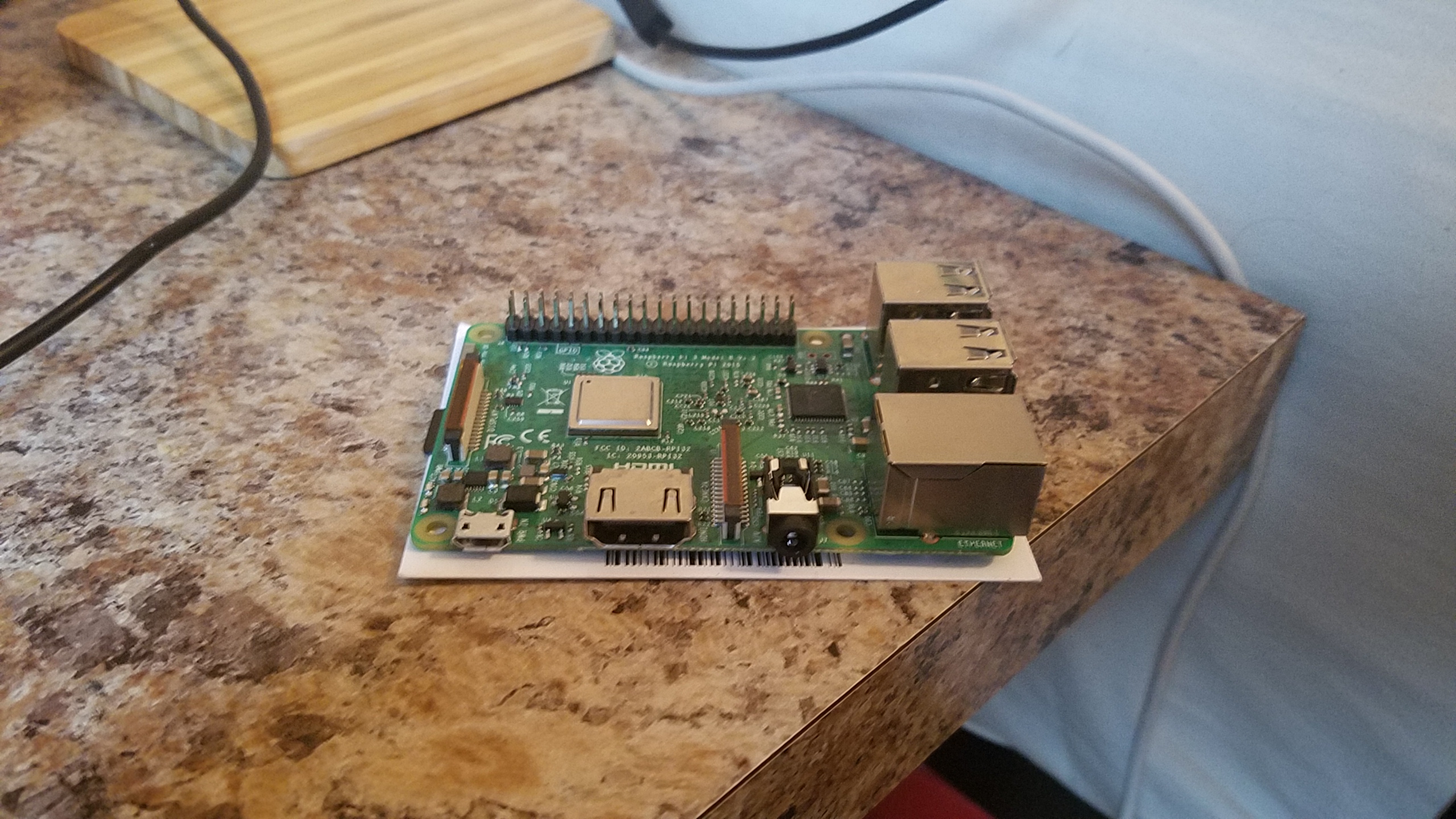
Ah Raspberry Pi, an awesome thirty five dollar computer the size of a credit card that can do oh so much. Before this assignment, I had been looking into getting a Raspberry Pi for quite a while, but never had an excuse to go out and purchase one, so when professor von Hollen assigned us this project, I was more than a little excited. I mean, it’s a credit card sized computer that could give a full desktop experience! And there is so much more you can do with it too, such as creating your own multimedia machine or making a server for your favorite video game.
I my Pi journey by uploading NOOBS on a microSD card after formatting it with SDFormatter, which was fairly easy as von Hollen gives pretty detailed instructions on how to do so. After turning on my Pi, I used the NOOBS software to install Raspbian for my Pi, just to see a sample of what this thing could do, and man, was I impressed. First off this OS came bundled with an early version of Minecraft, so that’s automatically 10 points to Pi. Since Raspbian is a Linux distro, I decided to do what all prominent programmers should when installing a new OS: make a ‘Hello World’ program. After that bit was done, I did some general we browsing to see how the Pi could handle day-to-day tasks, which, to its credit, it did fairly well. I only noticed some slowdown when trying to use more strenuous web applications such as YouTube.
From there, I had to come up with something much more useful for the Pi. My initial though was to turn the Pi into a Minecraft server for me and my friends, but after looking up some guides on how to do it, I realized the Pi 3 could only support older versions of Minecraft, and not the latest release, so I scrapped the idea. I then though about turning it into a multimedia machine so I could turn a TV into a smart TV, but I already had one in my house, and realized it wouldn’t be of much use to me. So, I decided on something more fun, a retro game device!
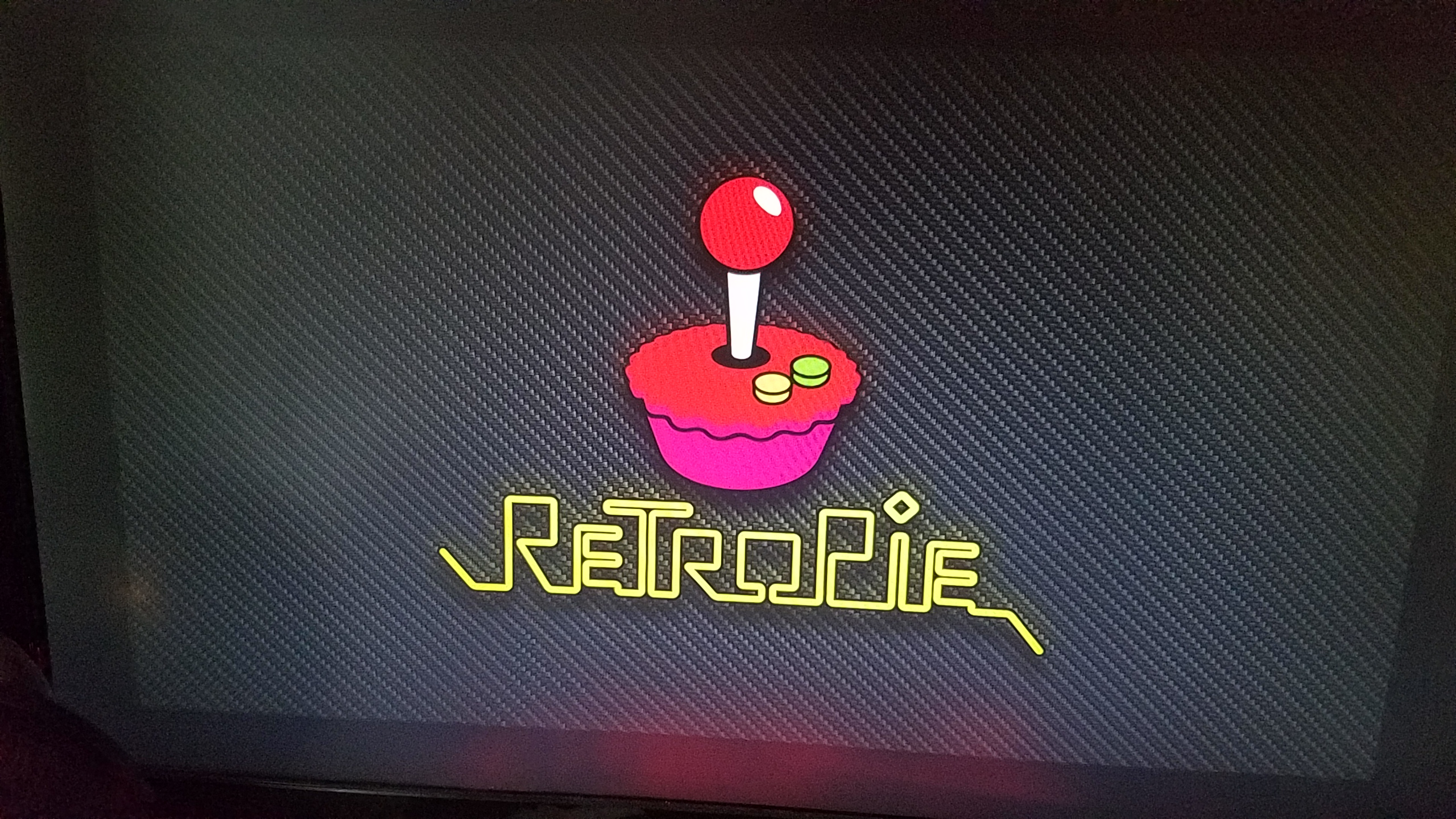
Enter RetroPie! An awesome, free OS for Raspberry Pi that is used to run retro game emulators and ROMs. I started by wiping my SD card so I could start fresh (so long Raspbian!). The method for which I was installing RetroPie is a bit different than the process for Raspbian, as the later could be installed using NOOBS, but the former required flashing to the SD card. For that, I used a neat little program called Balena Etcher that flashed the SD card in a matter of minutes.
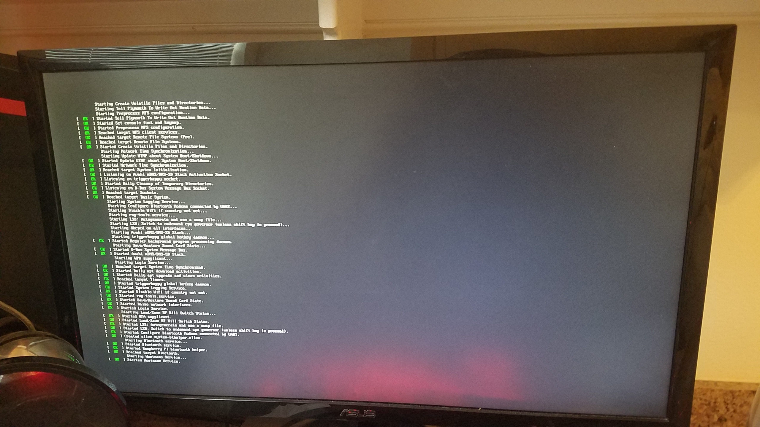
Next, I turned on the Pi to see if it flashed correctly:
WOO! It was working! Now, to install some ROMs. Before I go any further, I would like to say that I do not condone pirating video games without supporting the creators behind doing so. Any ROMs I have on this system I own in some form or another and have purchased (usually multiple times in the case of Nintendo ROMs), so please, support your creators! With that being said, I acquired some ROMs and tried to put them on my Pi… which is where the beginnings of my troubles began.
So, RetroPie is really cool in that it can automatically add ROMs from a flash drive to your SD card… as long as you have the file system set up correctly. So, usually you need to add a folder to your flash drive titled ‘RetroPie’ and then stick it in your Raspberry Pi so that it can add the necessary folders to add ROMs to, but I was having problems: the files weren’t being generated! I tried leaving the flash drive in the Pi longer, re-formatting the drive, but to no avail. Welp, it turns out my problem was on (of course) my part, as I had labeled the folder as ‘RetroPi’ instead of ‘RetroPie’. Yea… that’s an hour of trouble shooting down the toilet.
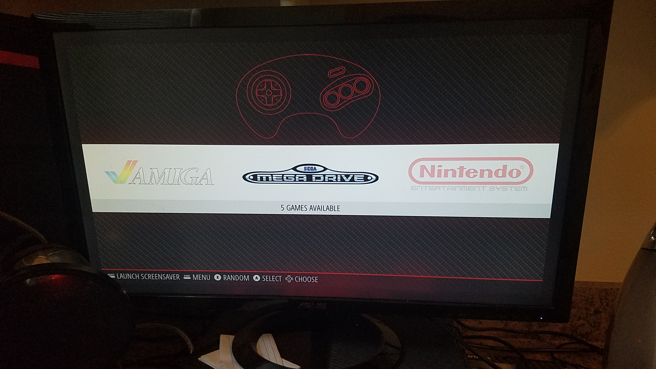
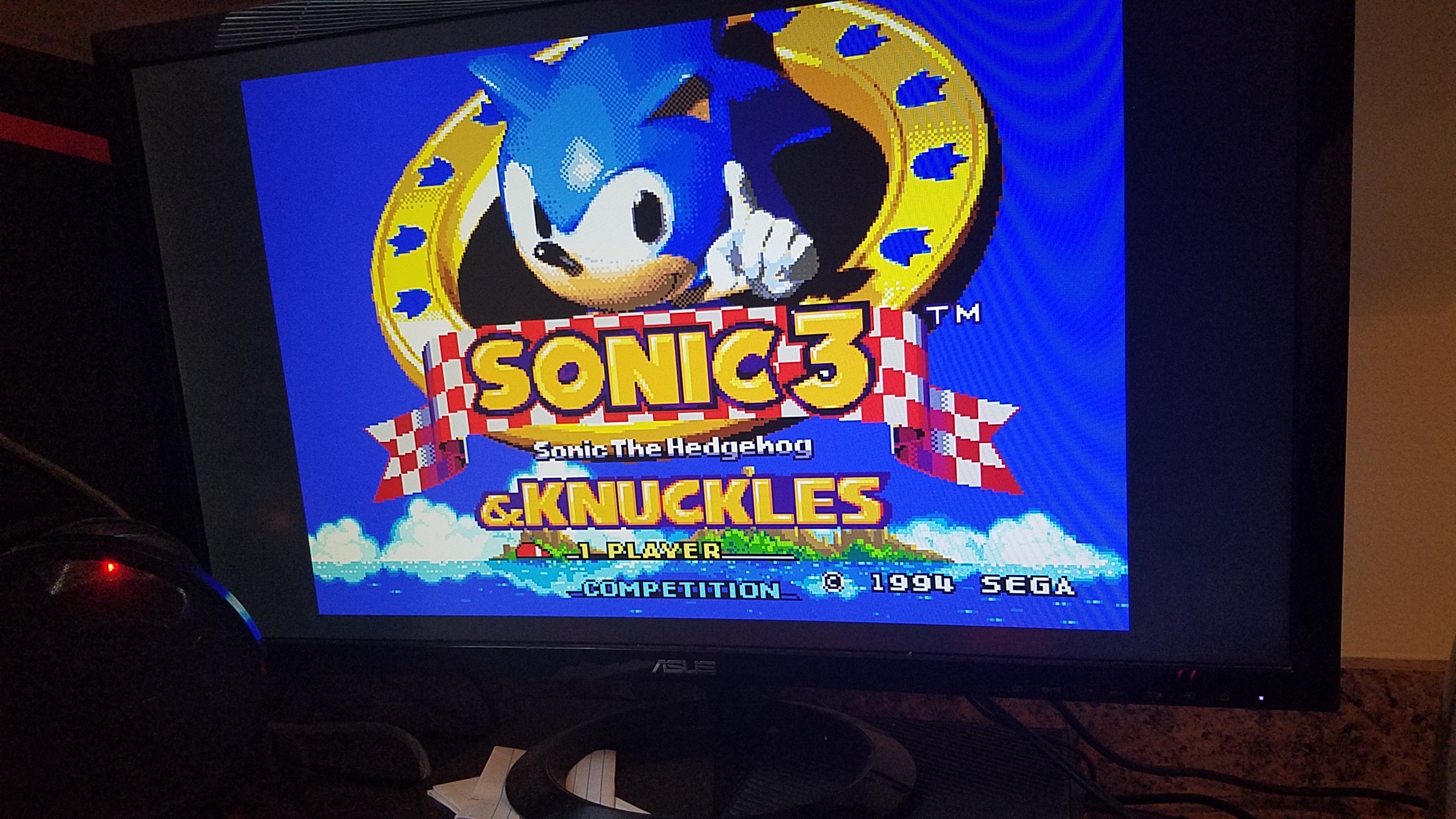
Next was the easy part, adding the ROMs to the appropriate folders on the flash drive and then sticking the drive back into the Pi so it could add the files to the Pi. This part was really easy, as the folders are labeled by game system, so adding the ROMs was as simple as clicking and dragging. This does require a little bit of knowledge about the history of systems in different regions however. See, in 1989 when Sega launched their 16 bit system, they name it the MegaDrive and launched it globally as such… except for North America, for which it was named the Genesis (an arguably cooler name). When looking for the folder to add Genesis games to, you will see there is no such folder, that’s because you must add it to the MegaDrive folder, as the Raspberry Pi was made in the U.K. as well as RetroPie. However, I already knew the Genesis as the Mega Drive as I have an interest in the history of video games and retro hardware, so it wasn’t much of a problem for me.
After putting the ROMs on the flash drive, all I had to do was turn the Pi back on and insert the flash drive and then restart the system and WABAM: I had some games on my Pi!
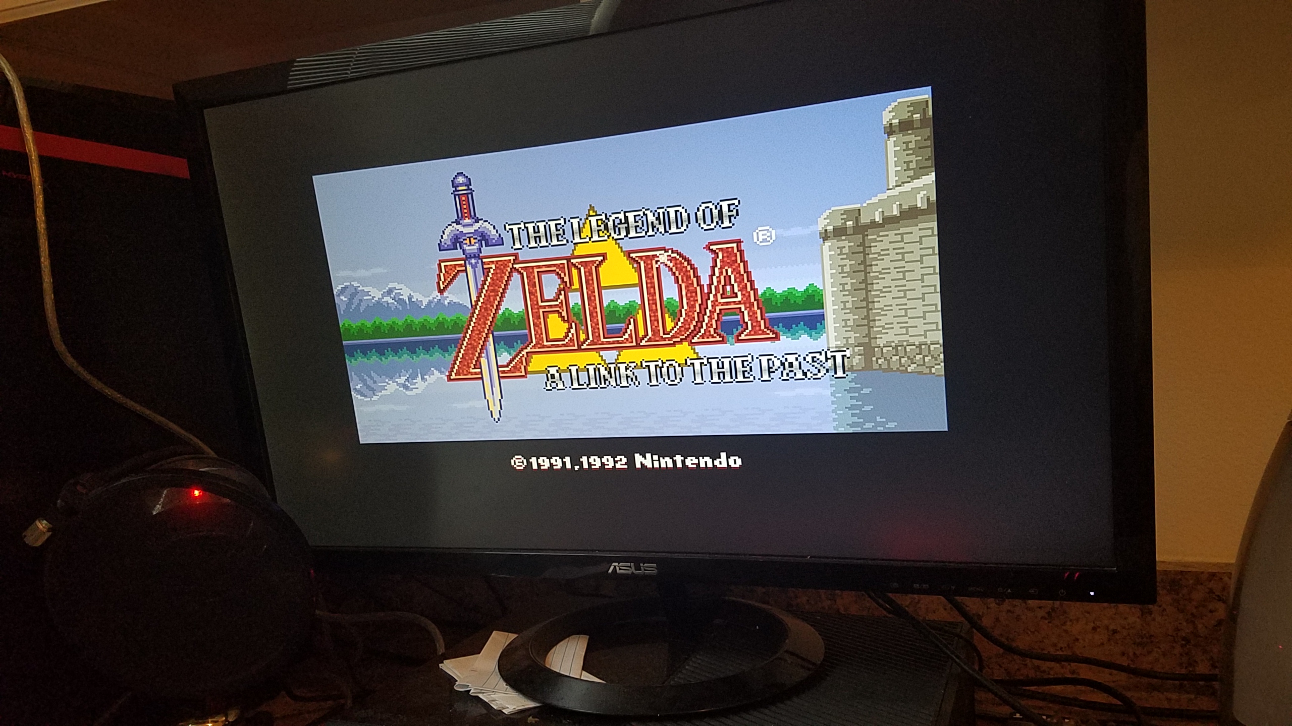
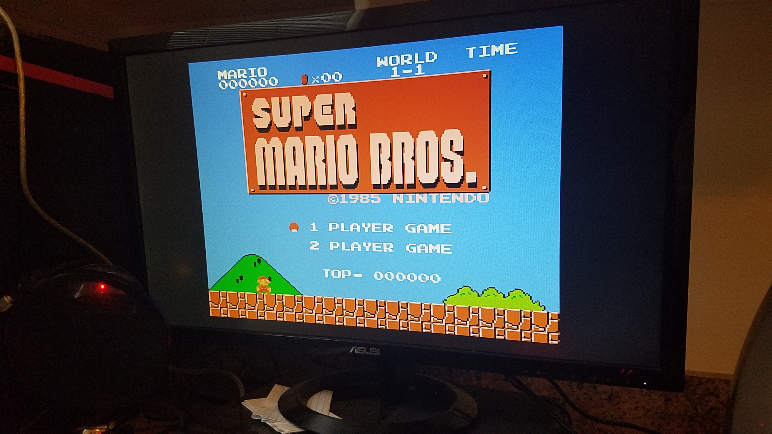
Also, what self respecting retro enthusiast wouldn’t have this original Super Mario Bros?
However, I noticed while trying out these games that I was running into a major issue: the quit game feature wasn’t working! Normally, you need to press start and select on a controller to quit a game and go back to the RetroPie menu, but for some reason, it wasn’t working on my system! I trouble shooted, reconfigured my controller inputs, but no dice. So, I took my problems to the only place I knew that could help me: internet forums. It turns out, the fastest was to fix my issue was to wipe my SD card and re-flash RetroPie on to my SD card, so I did. After doing so, all I had to do to get the games back on was to just stick the flash drive in the RetroPie and restart the system, as the folders and ROMs were already formatted correctly from before. After doing so, everything was finally working correctly!
Although this was a bit of a pain in the ass, I feel as though it was totally worth it. Being able to play games from yesteryear is an awesome experience, especially on a system that was one tenth of the size of some of the original consoles that it was emulating.
Well, that about wraps up part 1 of the two part finale that is this Emerging Tech blog. As always:
Hey everyone! It’s been a couple of weeks since my last blog post, and this week I’ll be submitting the last of them for von Hollen’s class! Sad, I know, but all good things must come to an end. So, without further ado, let’s get right into it!
For this blog post, I’m going to be going over a virtual reality project developed by Cameron and I! Originally, the project was going to be a ping pong multiplayer game, but there were issues with getting a bunch of the assets to work, as well as implementing certain feature, so the idea was scrapped and in its place, we made a ball rolling mini-game where you roll around a ball in a virtual space, all while trying to collect all the objects in the room. Here’s a video demonstration:
Cameron deserves majority of credit for this one. He put in a lot of hard work and effort to get this up and running in one day! So Lucas, make some note of that! As you can see, that game spawns a camera in the middle of the room, allowing you to look in all directions as you guide the ball using the joysticks, controlling very similarly to the Super Monkey Ball series developed by SEGA. After collecting all objects on the field, you will be rewarded with a ‘You Win’ screen telling you that… well, you won.
We ended up re-purposing the ping pong ball asset used in the original ping pong game for the player controlled object, as well as the walls and floor textures.
Well, that raps it up for another Emerging Tech Blog, and though this seems short, don’t fret, as we still have two other blogs to go through this week. As always…
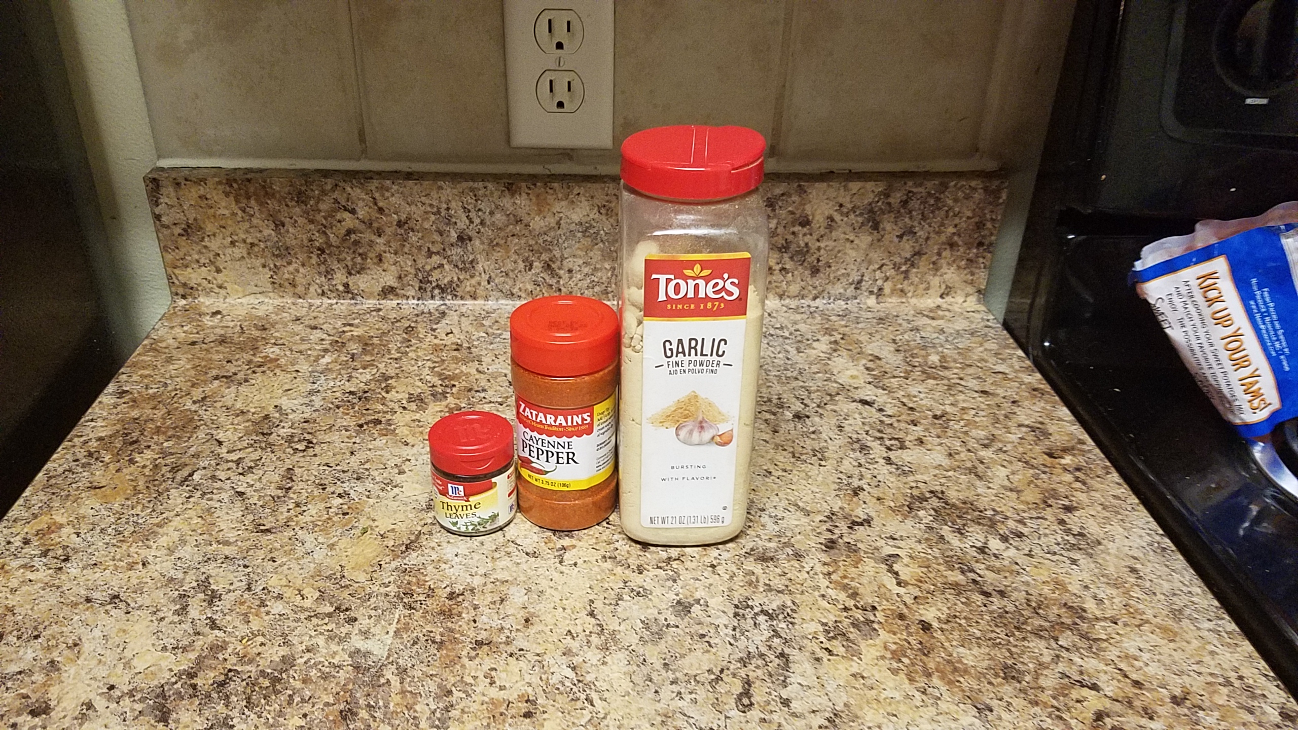
Welcome back to my dank dark corner of the interwebs, with a new week comes new blog posts, so let’s go ahead and get started. Last week I introduced a problem I’ve been having, which is to stay I’m a broke ass college student and cannot afford a spice rack, so I figured, ‘why not?’ and decided to model my own spice rack using Fusion360 and 3D print it later on when I had the chance. I started the modeling by taking some measurements of some of my spices in my cupboard. I wanted to have three different levels, one for smaller spices, one for medium sized spices, and one for large spices (pictured below):
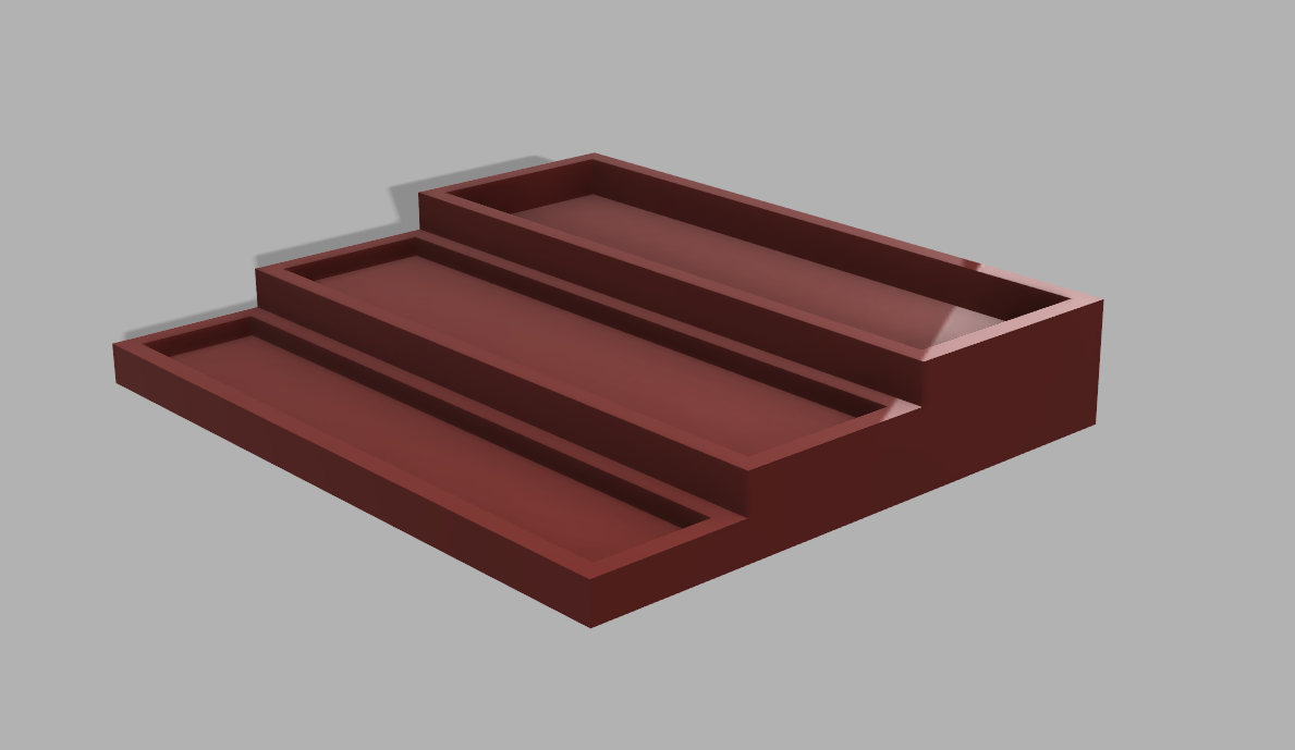
I figured the simplest way to do this is to make a stair-looking design in order to display the different levels:
I started by making a 350mm x 300mm x 60mm cube, and then started making cuts into the cube in order to place the spices in correct slots. The first row is 330mm x 60mm with a depth of 10mm, so that the spices won’t fall off the rack. The next tier up is 330mm x 80mm with a depth of 10mm again. The last tier is 330mm x 10mm with a depth of 20mm, as the larger spice was a lot taller compared to the other spices, and I wanted to keep it stable in the rack.
The design itself didn’t take all that long. Same with the modeling, as Fusion360 is pretty intuitive when it comes to cutting. Might of taken a bit longer if I was using something like freeCAD, but I intentionally designed this to be simple, so that there would be a lot less trouble when it came time to print, so even doing this in freeCAD wouldn’t of been that bad. Plus, I’m more of a function over form kind of guy, so while sure, I could of made it prettier, I preferred having the rack work really well with different sizes of spices, so a small compromise was made.
Honestly, making this was pretty fun. Required a little bit of brain power, but no headaches were involved thanks to Fusion. But until this thing is printed, I’ve got more spices to through in the cupboard.
Some days are better than others. There are days you ace an exam and feel on top of the world, and others where you realize you’re too poor to afford a spice rack…
So, I decided, screw it, if I can’t afford a spice rack, I may as well model and print one. I don’t think it should be too hard either. Now I can finally organize my spices instead of just chucking them in my pantry the way like the Philistine some people take me to be.
Also, I know what you’re thinking “Wow, two posts in one day!?! How awesome!” But before you get your hopes up, this blog post is going to be a short one. In fact it’s ending now.
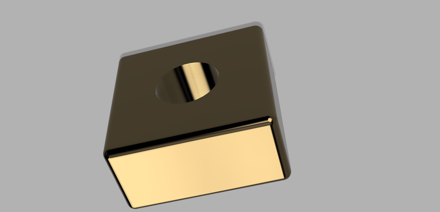
And we’re back, bringing you some more of that good good Emerging Tech blog posts. Don’t worry, this ones on me. On this weeks menu is Fusion360, another 3D modeling software but is thankfully much more user friendly than freeCAD. And what better way to begin working with a new 3D modeling software than to test it out with the hello-world equivalent to modeling projects, the cube with hole in middle:
Ain’t she perty? Fusion360 let’s you make some pretty good looking objects right in the program with it’s render function. This allows for some nice reflections and gives some texture to parts of your objects in order for it to look, well, more realistic.
Not so impressive, but the first object never is, so without further ado, let’s move on to the lamp shade:
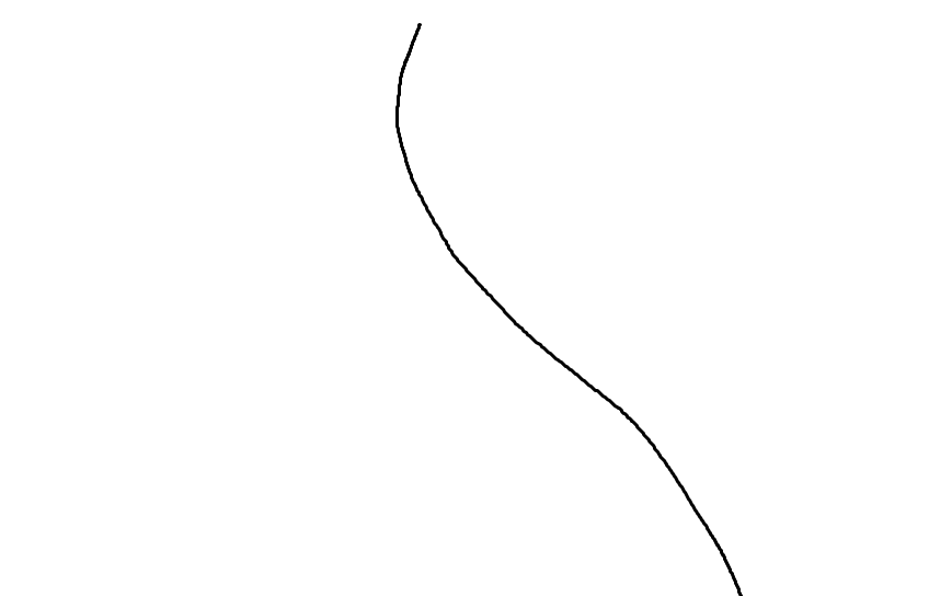
This was pretty interesting to make, actually. I started by making a little squiggly line in MS Paint, and importing it into the project so that I could make the general shape of the lamp shade:
It’s so beautiful, I could put it in a museum. After copying the the squiggle, I used the rotation tool to spin it on it’s y axis and wabam! A pretty awesome lamp shade was obtained. It seriously only took five minutes, and looks pretty nice.
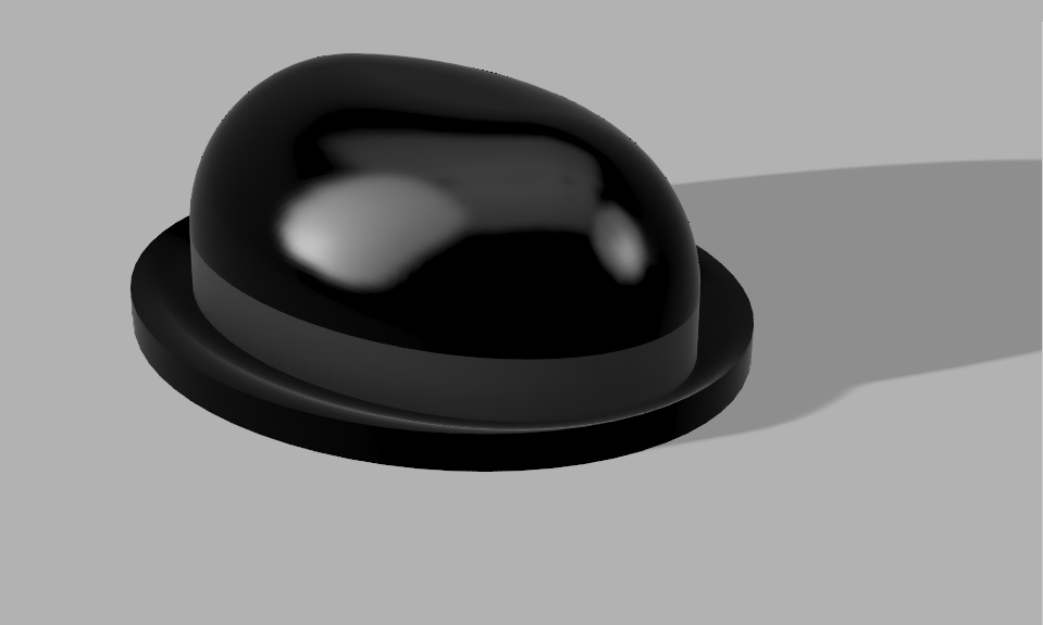
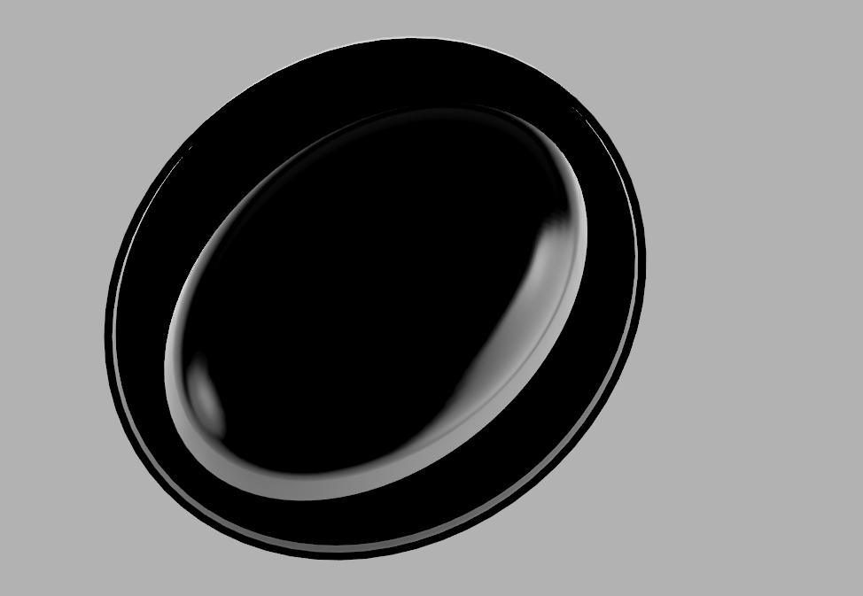
Now for a returning guest star! The bowler hat:
I put a fresh spot of polish on this sucker just for you guys! Look how it shines! How it gleams! A beautiful hat to perfectly top any ensemble.
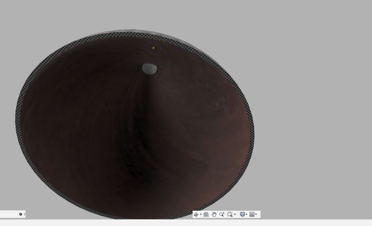
It’s even shiny on the inside! A polished dome for your dome!
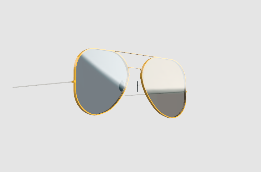
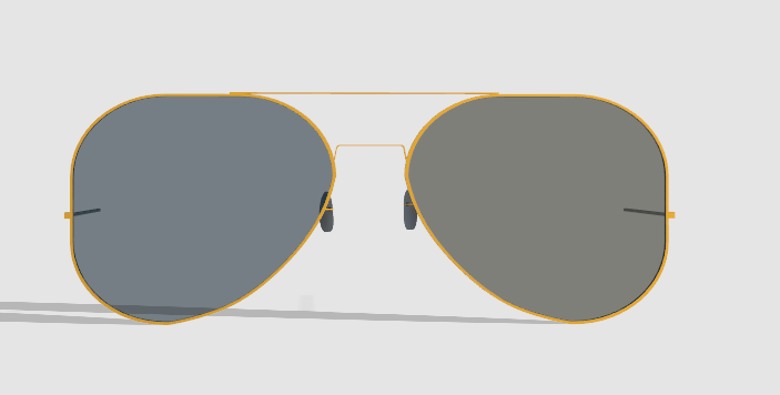
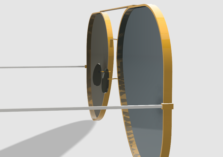
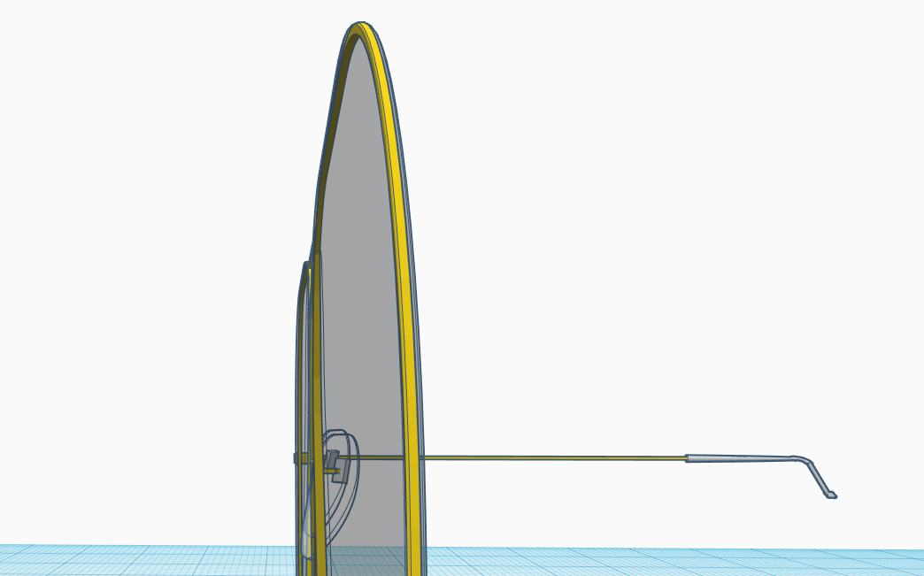
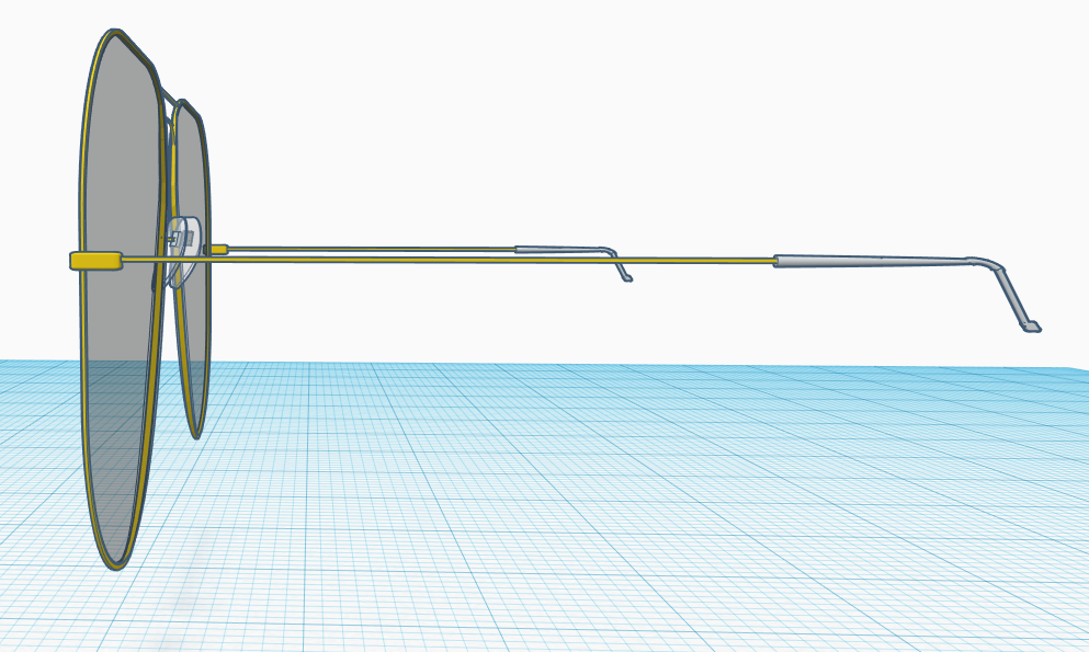
Last, but certainly not least, the aviators are back!
I actually took a pretty similar approach to how I did it in tinkerCAD. I started with the lenses again, made a slight cut in order to better get the shape of a lens, and then copied the shape and made it a little large, cut out the center, and boom, a lens with a frame.
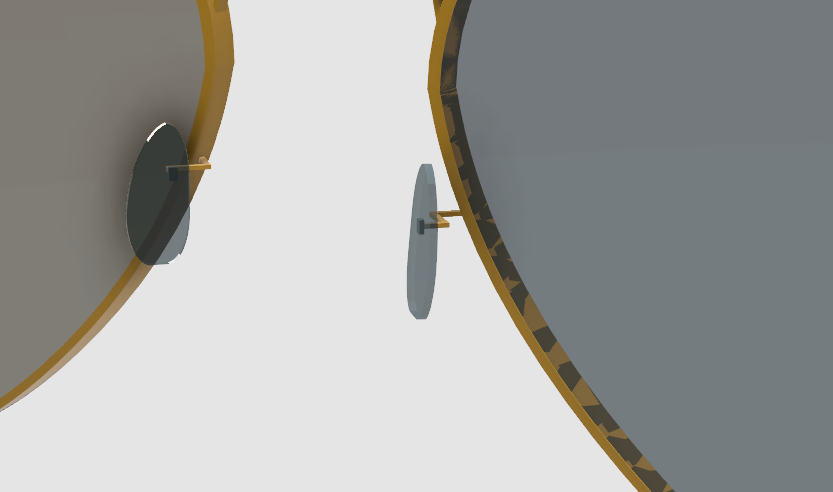
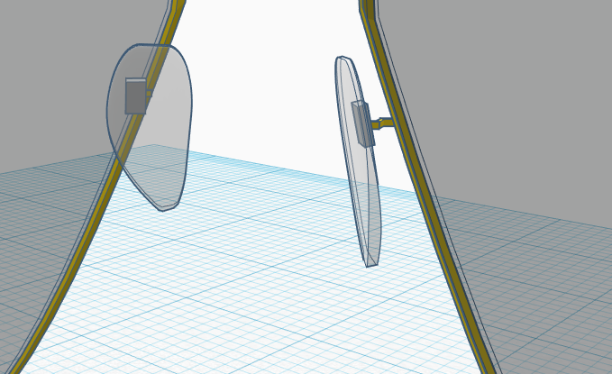
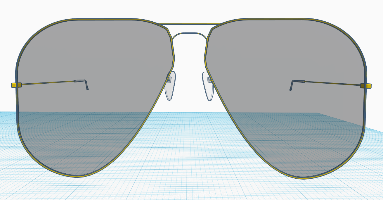
I also did that little trick with the nose pads where I took the lenses and reshaped them to fit. Hey, if it ain’t broke, don’t fix it.
I actually kind of prefer how to aviators came out in tinkerCAD, but then again, that software was for elementary schoolers, so of course it’s gonna be easier to use.
Another Emerging Tech blog in the books. I hope you enjoyed more 3D modeling stuff as much as I did, and until next time…
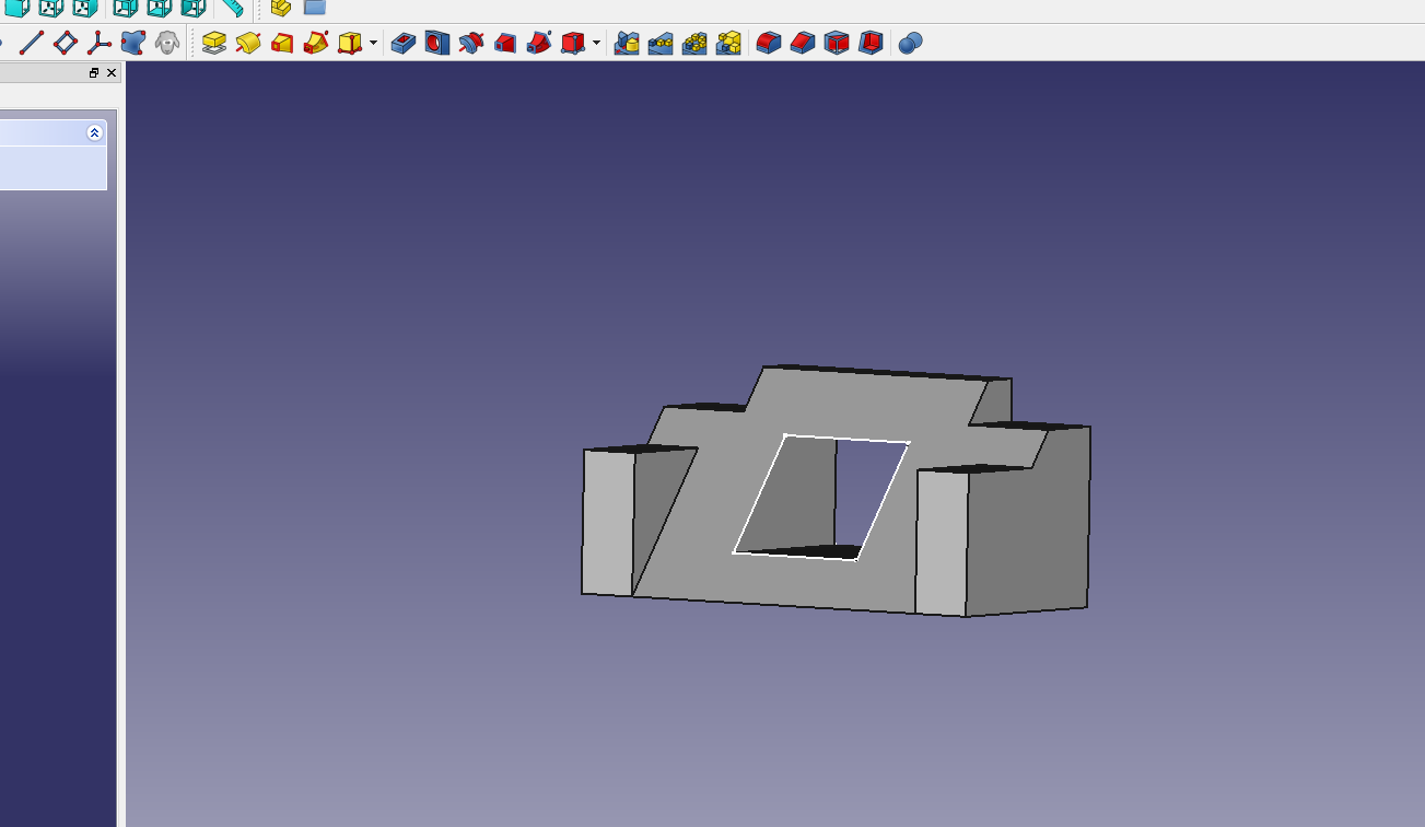
Welcome once more the two of you who read these blog posts! We are back once again with some Emerging Technologies and the return of 3-D modeling software. The software of this week happens non other to be tinkerCAD’s older brother, freeCAD. If I were to compare the two softwares, I would say that tinkerCAD is mostly for elementary students while freeCAD is for high school seniors and undergrads. Going from tinkerCAD to freeCAD does not translate well at all, mostly because of just how complex and jam packed with features freeCAD is. The entire control scheme is different, for one, aside from a few camera controls, such as moving the camera using the middle-mouse-button. The advantage of freeCAD’s complexity is that it gives you more finely tuned controls, once you get the hang of them, which don’t get me wrong does take some time and patience. How much time and patience, you may ask? Well, I spent a good two hours working on the tutorial, wading through crappy menu systems, sometimes works, other times doesn’t undo controls, and multiple crashes just to produce this little freakin’ thing:
You may be saying, “Hey, that’s actually not bad for two hours, looks kinda complex to make.” Well, how about this: I WAS FOLLOWING A TUTORIAL! One that, if you know how to do everything, should only take 5-10 minutes! Yes, a 5-10 minute project in freeCAD can take hours to do if you don’t where every menu item is, which, granted following the tutorial will teach you how to do, but sometimes, you don’t always have the same screen setup as the guy’s screen, because sometimes freeCAD likes to hide stuff based on window screen size, which can then take minutes of you precious time away from you. That and the crashes. Oh boy, the crashes. Look, I have a great setup here, 7th gen i5 processor with 12 gigs of DDR4 RAM and a pretty beefy graphics card, this thing crashed three times on me while I was working on this tutorial alone. Save early. Save often.
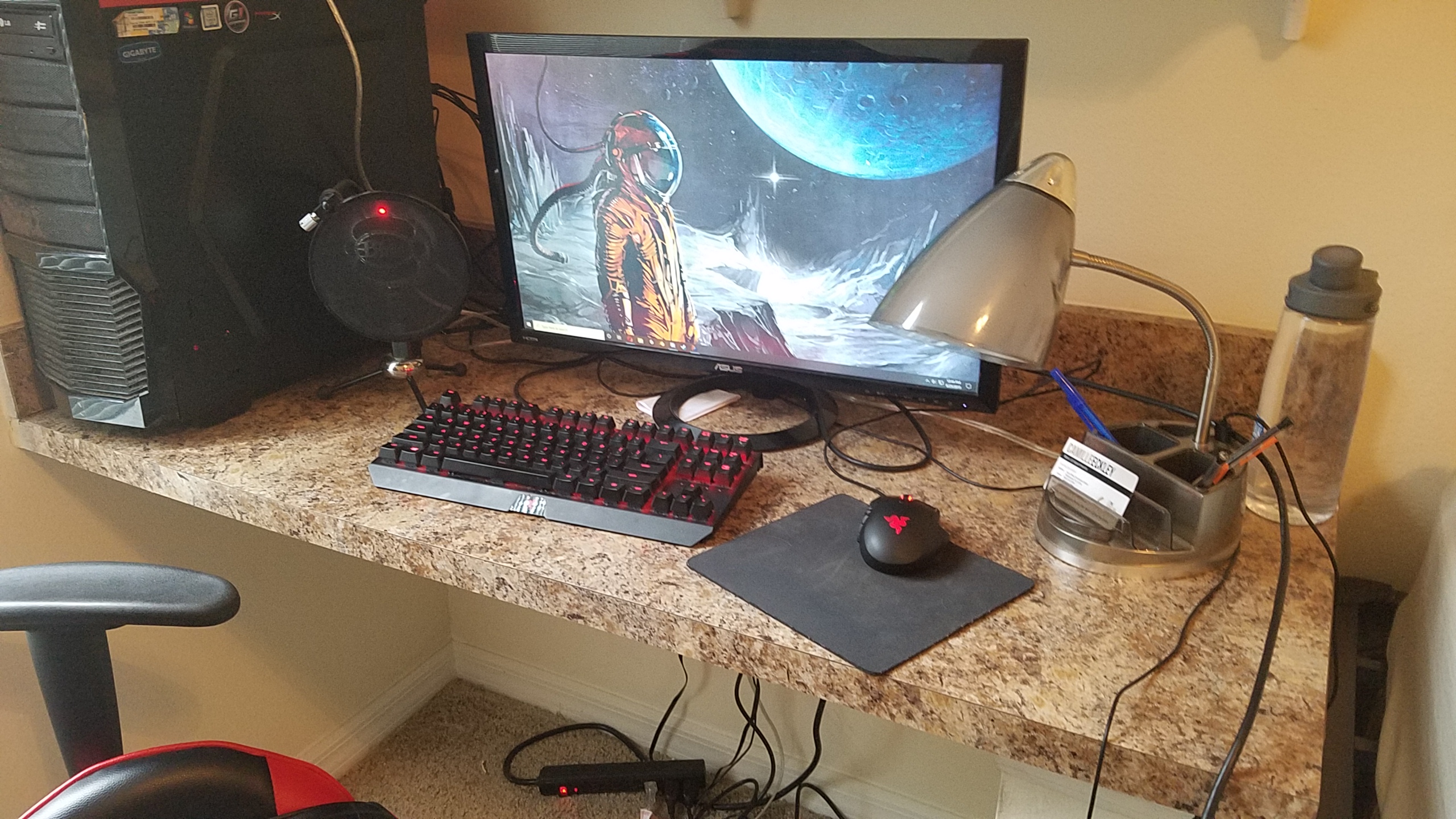
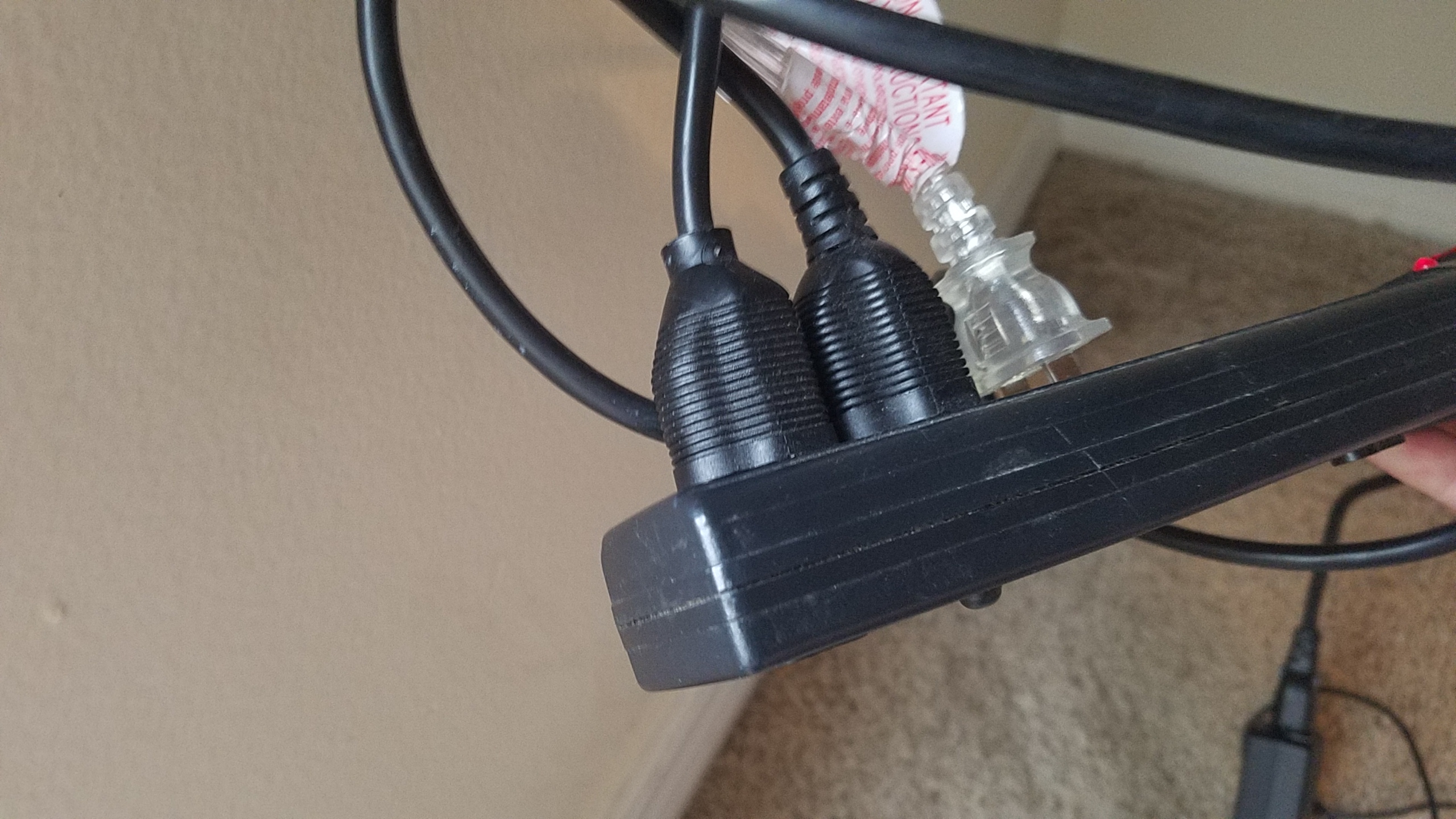
Moving on from the tutorial, my next task was to make a device that could hold on to the side of my desk, and hold a wire, so that it would not fall down to the ground. To be frank, this is something I needed anyways. Below is a picture of my desk:
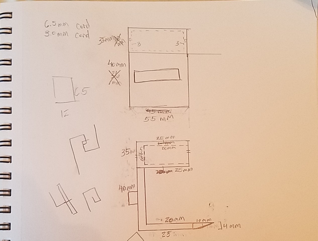
See that Ethernet and headphone cable? Those need to be organized! So, for this model, everything needed correct measurements, so I decided before doing any modeling, I would draw a rough sketch with measurements to scale. Here is a picture of the sketch:
As you can see, it was a crude sketch, as some of the measurements had to be adjusted, such as the 3.0 mm size for the circle based on the headphone cord, it ended up being 3.5 mm, etc. You may be wondering about that little box on the top with outlines on the inside? Well, since I was at it, I decided I wanted something a little nicer, and added a power strip holder for my computer desk at the top. It does come at the cost of losing one of the electrical sockets on the strip, which in my case isn’t that bad. A pic of the strip is was designed to be used with:
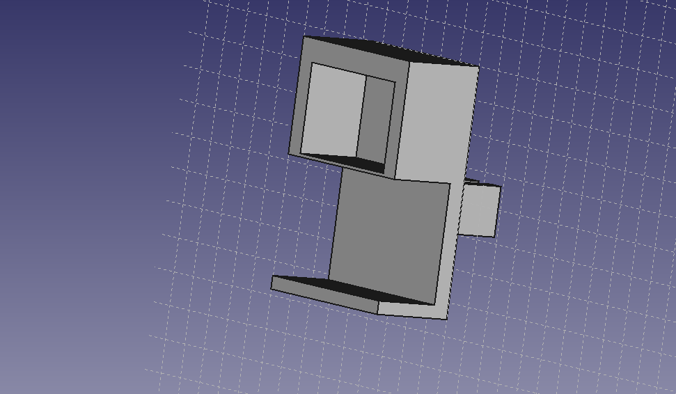
Don’t worry OCD people, I plugged the clear cord all the way in later. So, without further ado, here is the object:
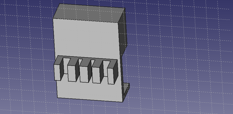
As you can see, it has a very basic design, function over form. The square cutout on the top is just large enough to fit in the power-strip’s base. This took a little longer than the tutorial to make, but that was mostly due to me restarting it a few times after realizing I should have made certain parts larger, and deciding against making the top a separate piece from the bottom, and certainly the two crashes didn’t help, but I digress. Moving towards the back, I added four slots, two slots for 3.5 mm cords and two slots for 6.5 mm cords:
I tried to put as many as I could on there as to not waste space and I think it came out pretty nice. I originally had an idea for a circular design, but it was too complicated so I remembered to old adage, “keep it simple for stupid, and I’m stupid”, so I went with a much more basic design that allowed me to easily fit multiple different cord sizes.
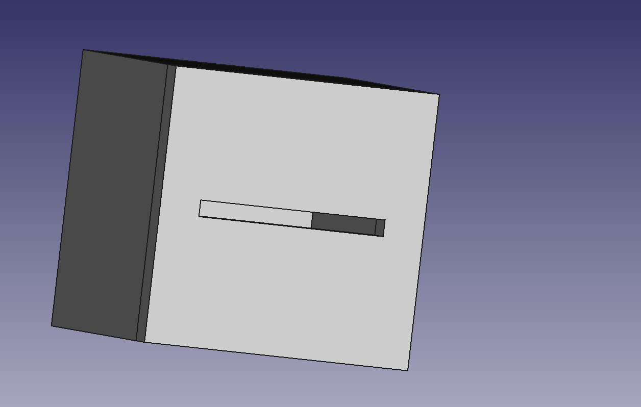
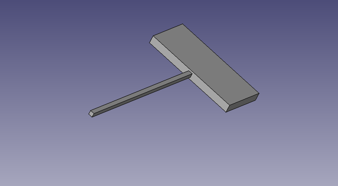
For the last part, I needed to create two separate objects, that when connected together, would not fall apart when held regularly and upside down. I though, “Hey, you know what would work really easily and would be simple to make? Lock and key.” And that’s what I did, very rudimentary, really isn’t even a lock, just kinda a hollow block with slit that’s made perfectly to fit the key:
There’s enough room inside the box so that you can turn the key and it won’t fall out. It does the job and it does it well. As you can see, All I needed to do was make a large cube, make another cube that was 5mm smaller on all sides and use the power of VOID to hollow it all. From there, was just making a top with a slit for the key. The key was hard to make either, but the placement of ‘handle’ require a little bit of math, so there’s that.
That about wraps up another emerging tech blog, and as always…
It appears it is that time again strangers from the Internet, blog post. On this weeks agenda: tinkerCAD. It’s another made for elementary student applications, but unlike our previous friend appInventor, tinkerCAD is surprisingly fun to mess around with. The way you create objects and shapes is fairly intuitive and it really is what you see is what you get, or perhaps what you don’t see as well, but that understanding comes with embracing the void…
That sounds a bit ominous, let me rephrase. In tinkerCAD, and other like 3-D modeling software, you can create an object and assign it to be negative space, in the case of tinkerCAD, they call it a hole. You place this hole inside another object, and when you combine the two objects into one, a hole will be made in the shape of your ‘hole’ object inside of the object it was placed within.
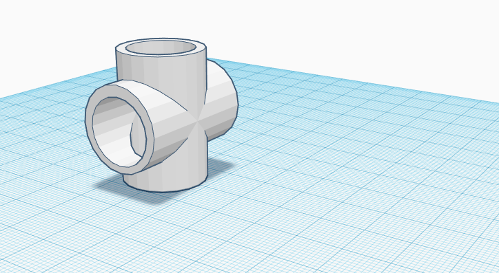
Below are the fruits of my labor, first a basic PVC Pipe intersection piece:
Not bad eh? Well, we all got to start somewhere, and wait till you see my next creation!
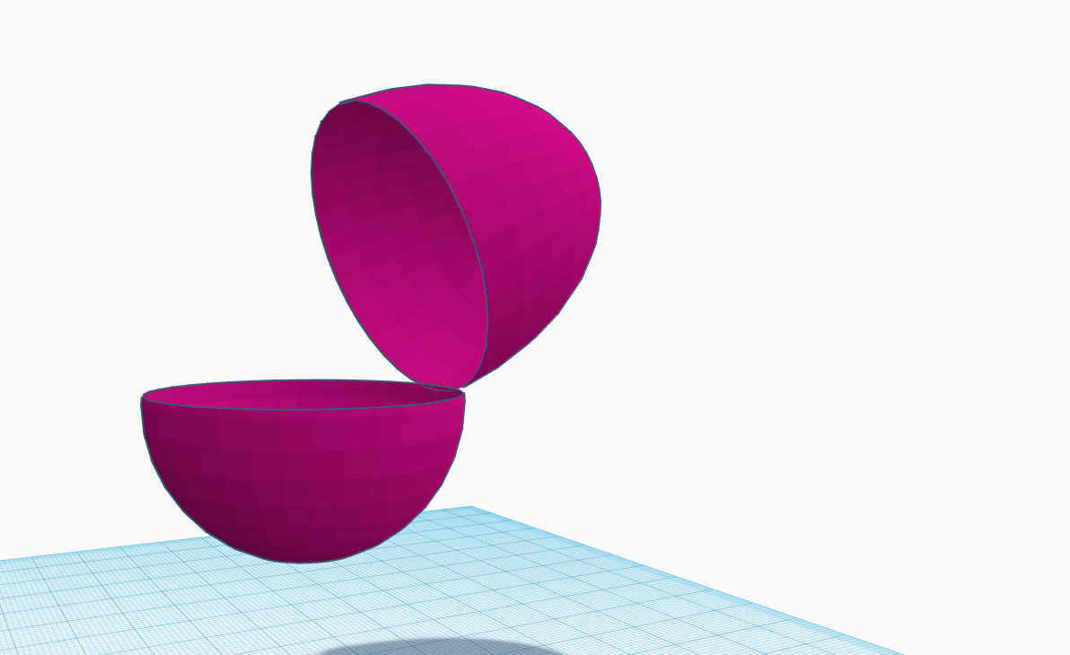
EXCELSIOR! BEHOLD, EGG, HOLLOW AND ALL!
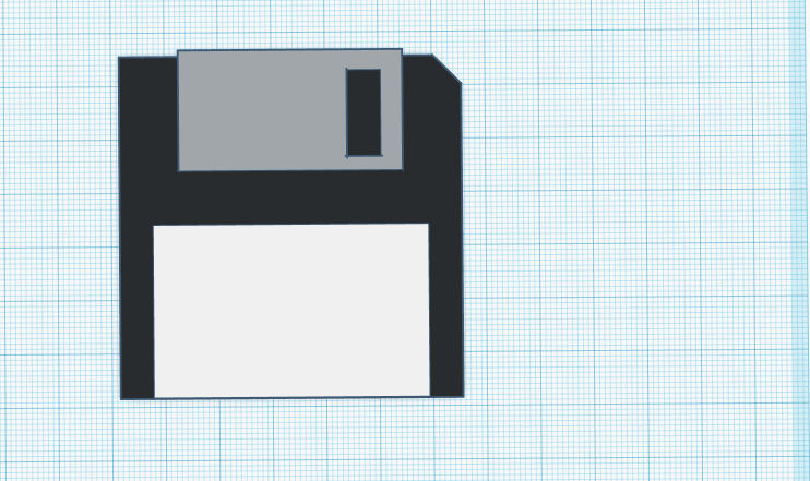
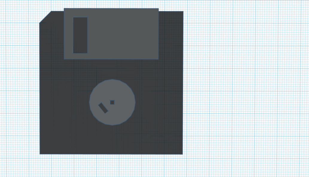
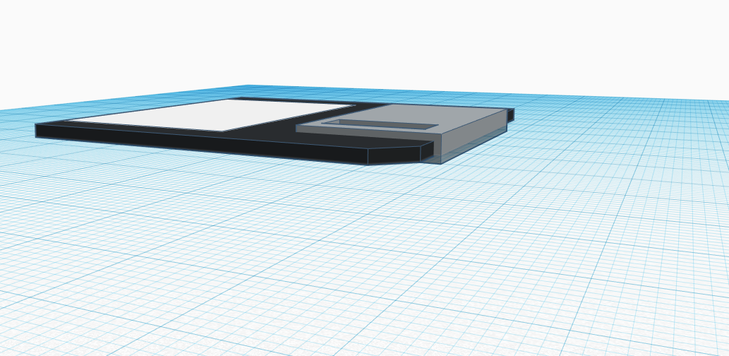
…tough crowd. Well good news for you, we can save all complaints about these two pieces to this handy external storage device I made. It can hold up to 2048 kilobytes of data, impressive uh?
I was particularly proud of how I got the width of the objects to be pretty accurate, I will say the white identification sticker on the front was a bit finicky, as it would glitch into the surface of the actual floppy, but adjustments of width did the trick:
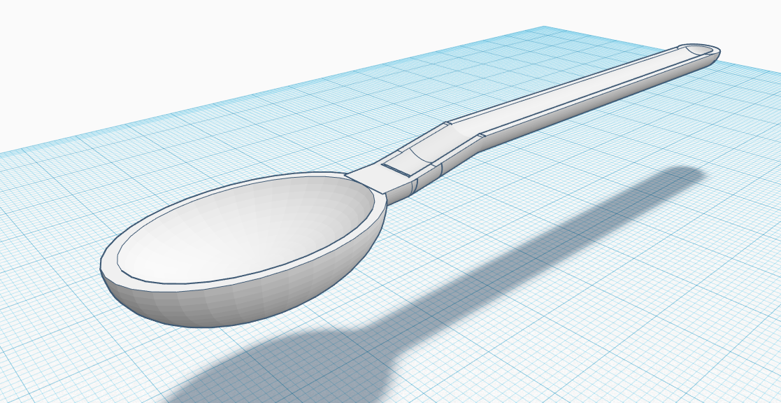
Next, the dreaded spoon. Behold its concavity and admire its white sheen. Soup, cereal, ice-cream, nothing can stop this mighty utensil:
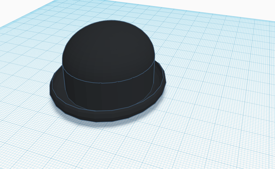
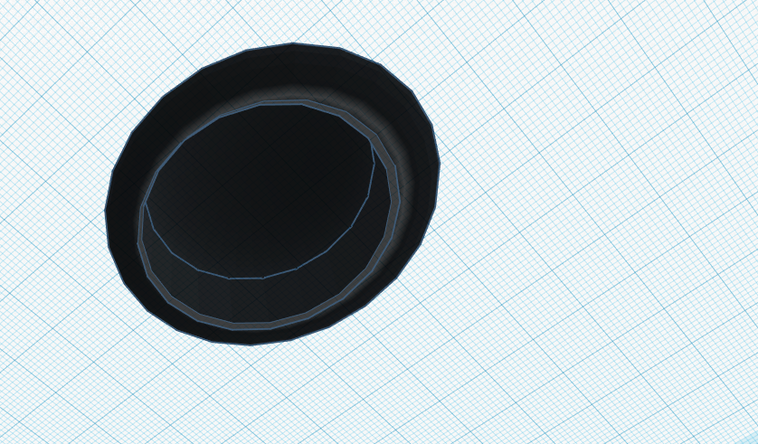
Of course, you cannot dine on some delicious gazpacho without a warm bowler hat to keep you cozy, so I made one just for you! Go ahead, try it on! I want to see how it looks on you!
Make sure it isn’t too small for your head!
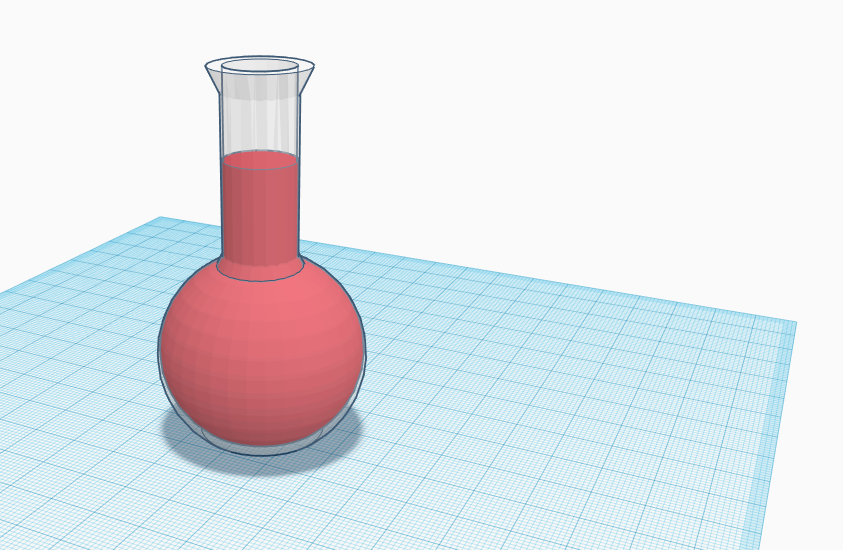
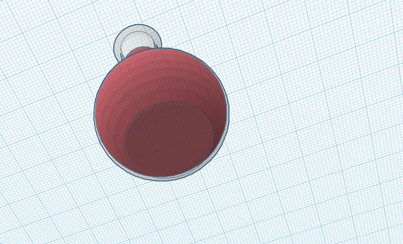
Oh wait, you might need something to drink. Do you mind Mountain Dew Code Red? I don’t have any clean cups, but you can use this handy scientific flask I had next to my medicine cabinet:
Also, don’t worry, it won’t tip over, it has a flat base. Make sure to use a coaster.
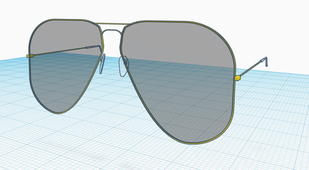
My last piece, and the one I had the most fun working on was the Aviator glasses:
These sure took a while, but in the end I felt like it was worth it. The atual lenses them selves were a pain to begin with, and I ended up using a flat square, added some rounded edges and cut off the bottom left side by first making cutting tool using a parabola-hole on the square and using the cut off piece to then cut the actual lenses, thus giving it that off round shape. Adding the frames to the glasses took some work, especially because I had some clipping issues, but I managed to make it look fine. Plus I had some width to the lenses so that it looks like glass from the side:
The making of the rubber ends of the arms of the glasses took some time, and a lot of void power but gives it a much more authentic look than just having a little end-cap on it:
For the nose pads, I pulled a little tricky on ya! I took the lenses for the glasses and reshaped them in order for it to have a realistic shape. I then added some width to give it a more realistic look and some wire coming off the frames with a square bracket for the pads to lock on to:
I was pretty surprised at how well I pulled off the aviators considering before this I only had a tiny bit of experience with another 3-D modeling software called blender.
Unlike appInventor, which had loads of frustrations in the start trying to get the emulator just to test your applications to work, which gave way to some barrier of entry, tinkerCAD just lets you get to work without having to install any sort of external software package, just go and start working. I know the hell that is freeCAD awaits me next, but for now, I’m pretty happy with 3-D modeling and look forward to doing some more.
That wraps up another Emerging Technologies update, until next time.
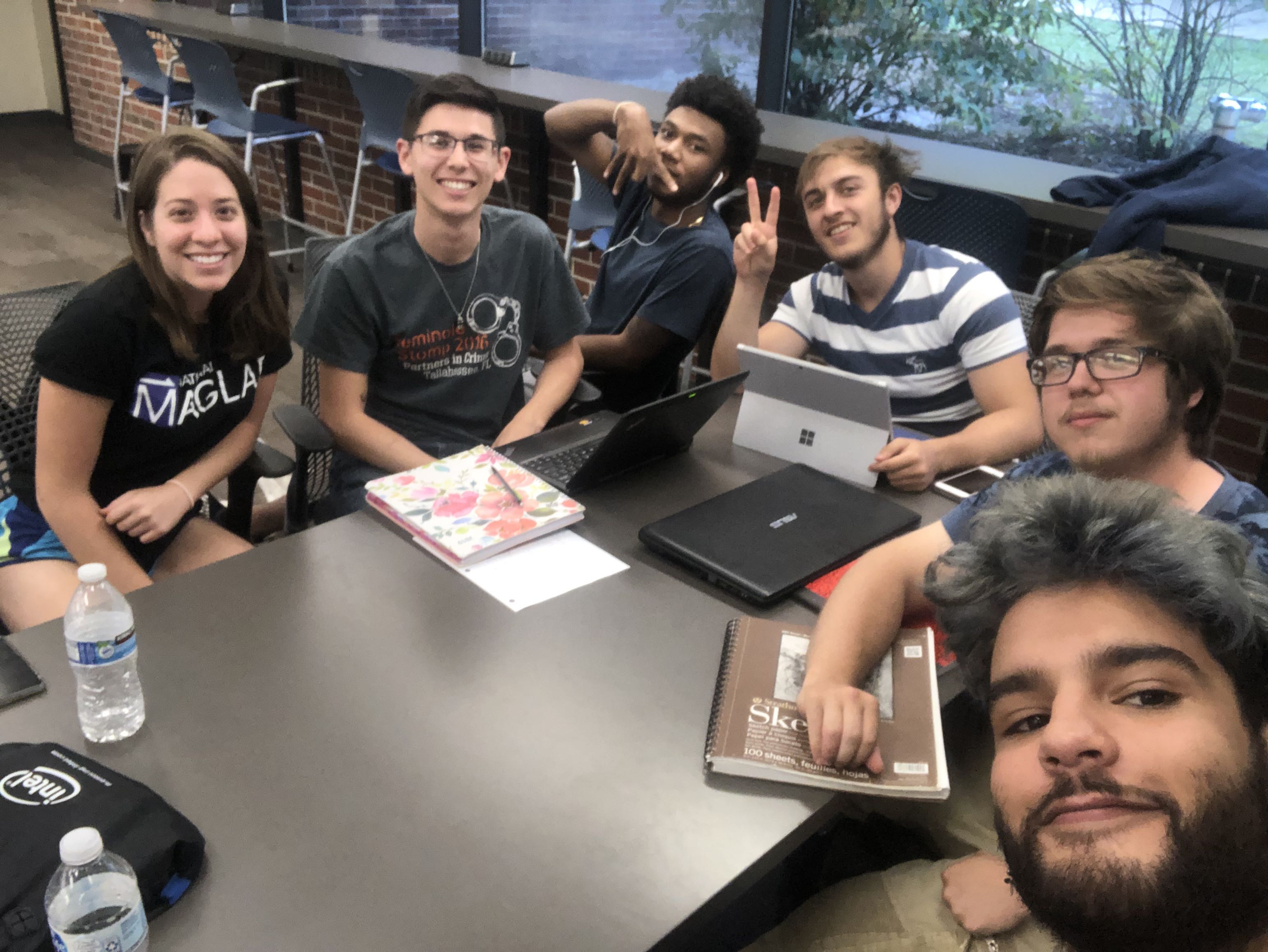
Time for a brand new blog post, fellas, so strap in. This week, I’ve been working again with our favorite application building device for fourth graders, AppInventor. However, this time I was not alone, as I was/am on a team with five other individuals to make an app of our choosing. We decided on a shooting gallery type game involving political members of Venezuela with the title being ‘Political Punisher’. After talking over some basics about what we wanted the app to be, we all agreed to meet the next day to discuss the scope of our project and some of the smaller features and about how we would go about dividing up the work. So, next day rolls around, and we all meet up and start dividing up the work. Obligatory selfie of us all together:
Me, on the right with the glasses
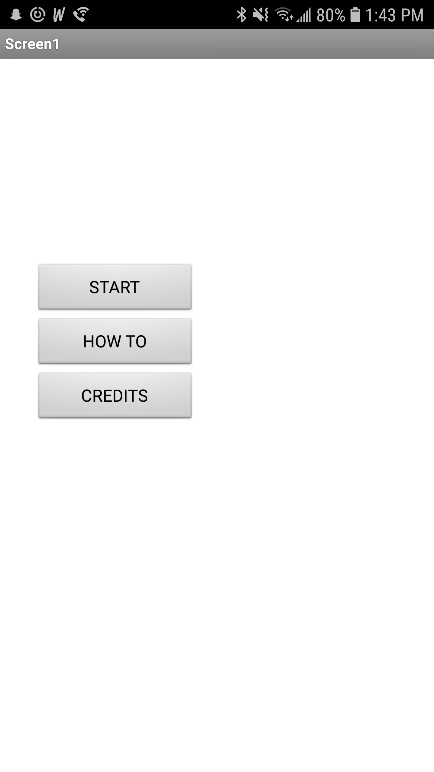
Since I had the most experience with programming (number 5 gang!) I was tasked with developing a slingshot system so we could ‘throw’ rocks at the targets in the game. We agreed to use a shared gmail account so that we could all login to AppInventor and work at our own leisure. It was also decided that we would upload the assets we needed into the google drive associated with that gmail, in order to make our lives a little simpler. With that, I started work on a title screen… the first of my bumps in the road. It turns out that one of our group members started working on a demo in the project file, but the demo was set to the opening screen of the app, and the only way to change it was to copy all the blocks and assets to another screen and then delete that screen, so in order to save time, I ended up creating a another project file so that I wouldn’t accidentally delete any data or blocks. At least with that, we could port over any blocks that were developed in the original project file to the new one.
Finally I had a title screen, with working buttons mind you! It was perfectly lined up in the AppInventor design window, it looked beautiful… then I uploaded the project on to my Samsung device and found it to be… a little off:
Oh well, at least the buttons work!
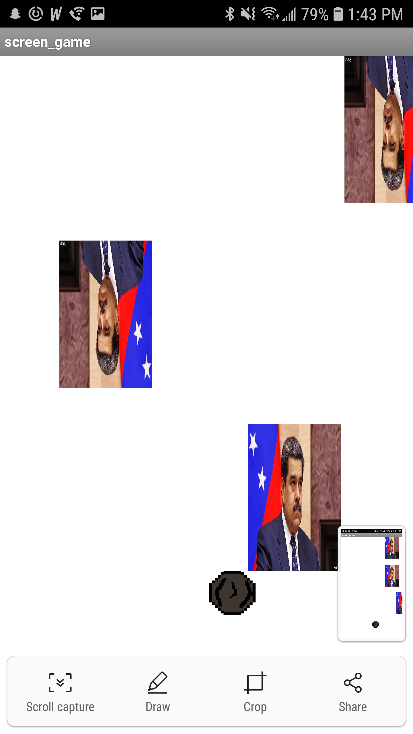
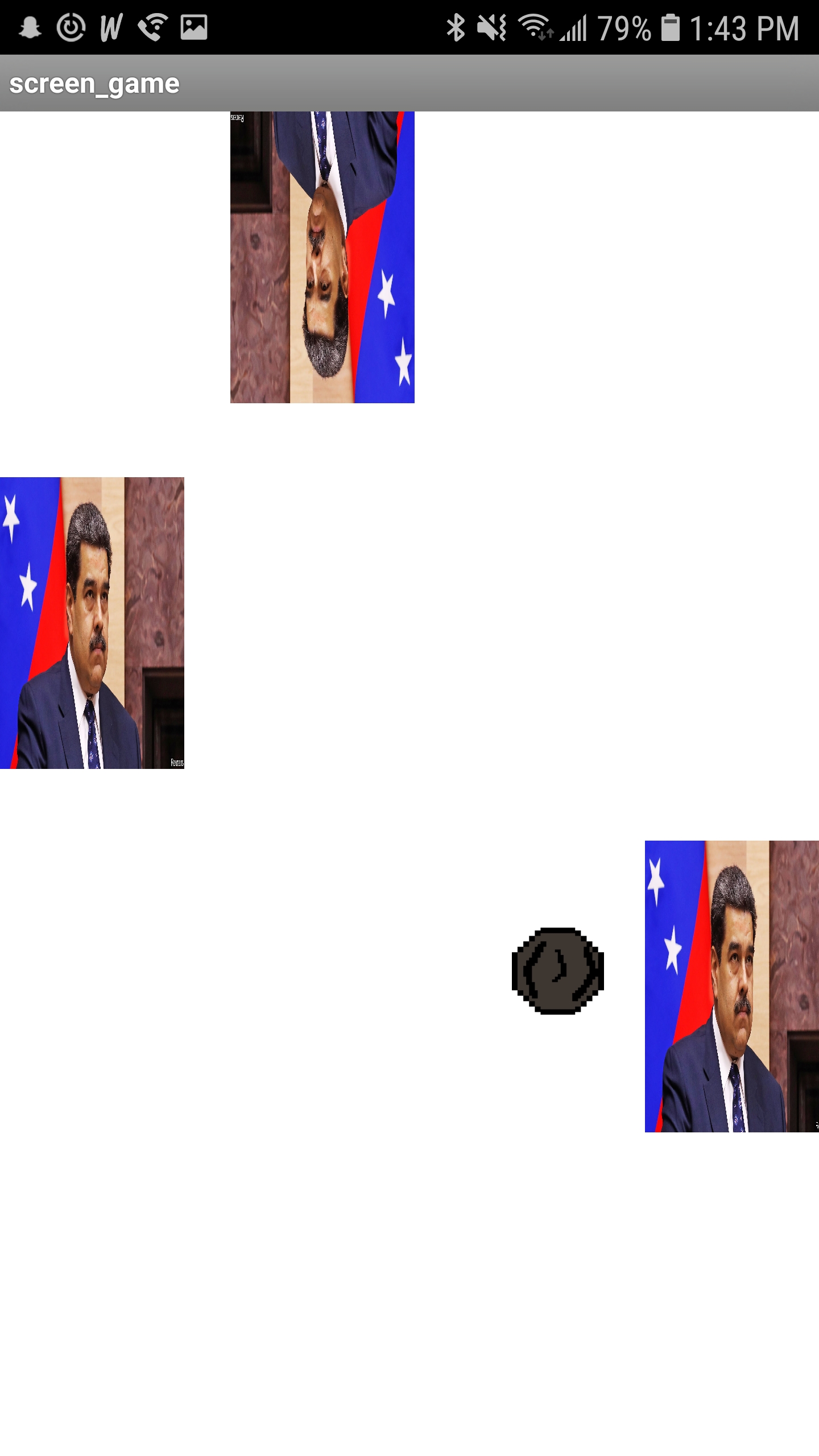
Next I added the a back button feature to each of the screens so that you could go back to title without the need for a button on the screen, for testing purposes. Next, it was time for the main event, the slingshot implementation. To start, I made a small sprite for the rock in a free sprite editor web application I found online (for free). To implement the slingshot, I repurposed some code I found from an AngryBirds tutorial online, but I had to change a bit of the code in order for it to match up with the orientation of the screen, placement of the slingshot, and angle of the shot, considering you have to shoot the rock in the air as opposed to shooting a bird across a screen. I haven’t been able to implement gravity yet, but the slingshot is completely up and running, some screen shots below:
I ended up getting the slingshot finished on Tuesday morning, to which we met up again on that day and discussed what we wanted to present for the App Test day, and implemented what we could during the time. Before the meeting, I added edge collision so the the rock would respawn after hitting the edge of the screen. Using the block as a base, I ended up helping one of our teammates with enemy collision as well, which is up and running as of now!
Well, I think that about wraps it up for the blog post for this week. As always, stay golden Ponyboy.
Hey folks, I’m back at it again with a fresh new blog post, so grab some afternoon java and let’s dive into some Emerging Technologies info. Taking things a step back to Wednesday last week, I was working with this nifty tool designed for third graders called AppInventor. It was real neat as it allowed you to go from nothing to a, albeit, more than often bare-bones, complete app for android. What is not so neat about it is that the android emulator designed to work with the app can make you feel less intelligent than the third graders this webapp was designed for.
Throughout class on Wednesday, I spent my time going through documentation on how to get the emulator up and running with my linux machine (yes it is mint, and I don’t care that it’s on a laptop!). After searching for forty minutes on-line, I found the only feasible solution was to perform a fresh install of the emulator and try again… damn you, AppInventor. With a fresh install on the emulator up and running on my laptop, I could finally get to work… once I figured out how to get an app from AppInventor running on the emulator. Yet, another hurdle.
This time, I was able to find a quick video YouTube for how to do it, so my headache did not evolve into a migraine. Below is a picture of the slowgoing.apk app we made in class together working on the emulator:
With
that out of the way, I had a whole twenty minutes to actually try
making something in AppInventor for the day, so I tried making a
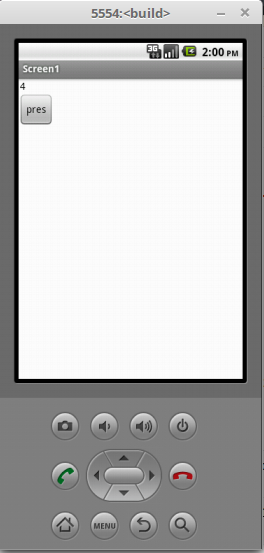
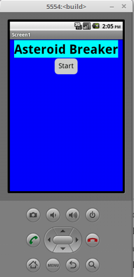
simple game where a meteors would fly across the screen and you had
to click or touch them to make them disappear before leaving the
screen… I barely got past the title screen by the time class ended,
but it has a cool blue background and changes screens, so that’s
cool. Here’s a shot of the title screen, button and all:
That about wraps it up for this weeks blog post. Don’t fret though, a new blog post will be around shortly enough. Until next time…